Network Tracing
An additional license is required to access the Network Tracing toolbar
Overview
Depending on your organisation and these tools perform network tracing operations on prepared network data.
The trace toolbar can be used for a few scenarios but the primary purpose is to allow utilities to map out their asset networks to plan for network outages or unplanned outages. This will form part of a process to report on outages and notify customers/residents.
Other possible scenarios for these tools include:
- Event planning whereby roads are closed and residents are notified
- River flow mapping
Network Tracing Concept
Network tracing is a process that traverses a hierarchical network i.e. pits / pipes etc.
The hierarchical network is composed of connected edges (lines) and nodes (points).
The trace compiles a set of edges that connect to the initial start edge.
The trace can be limited in extent by defining break points at nodes in the network

Run Trace |
Run Network Trace from selected network edge. |
Isolation Off |
Engages Isolation Mode. This mode will force nodes of a particular type (i.e. valves) to become break points in the network. The isolation node types are defined within the Network Trace configuration. |
Operability Mode |
Engage Operability Mode. This mode will override break points / continue nodes based on whether a node "is operable". e.g. If a valve is broken and cannot be shut and is recorded in the data then the trace will pass through this point even when running in Isolation mode. |
Break Point |
Allows you to define a break in the network. Break points can be any node in the network. The trace will stop at this node. |
Continue |
Allows you to remove a break point. |
Clear Modifications |
Clears all break points you have defined in the network. |
Property Link |
Selects properties linked to the current set of network edges. |


Usage Examples
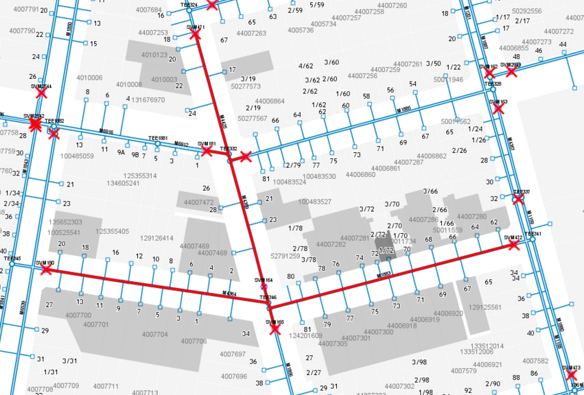
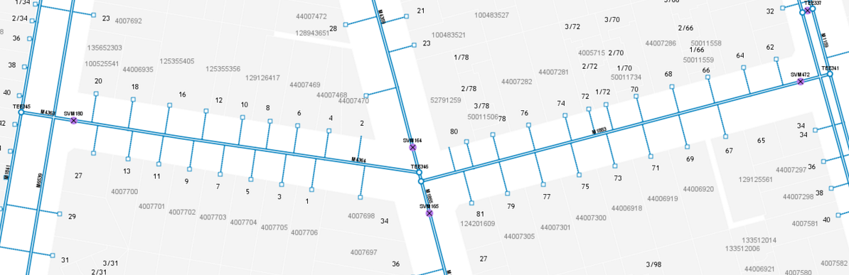
Simple trace
In this case, we want to select all features Tee'ing from the larger network to capture the branch.
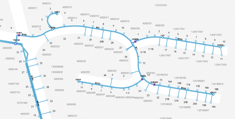
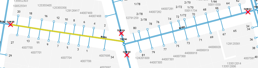
We add a break point at node TEE 1930 and select an edge within the branch
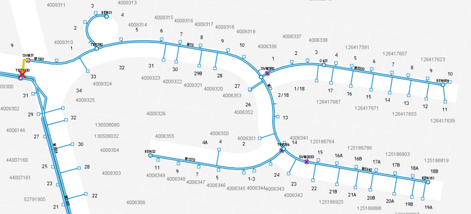
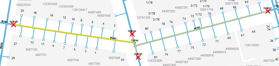
Now run a trace to capture the complete branch
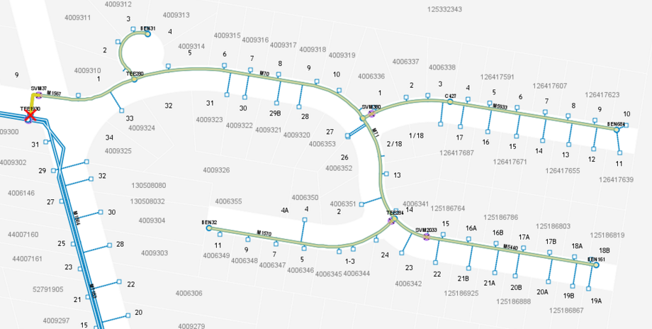
We can link to selected properties using the property link function
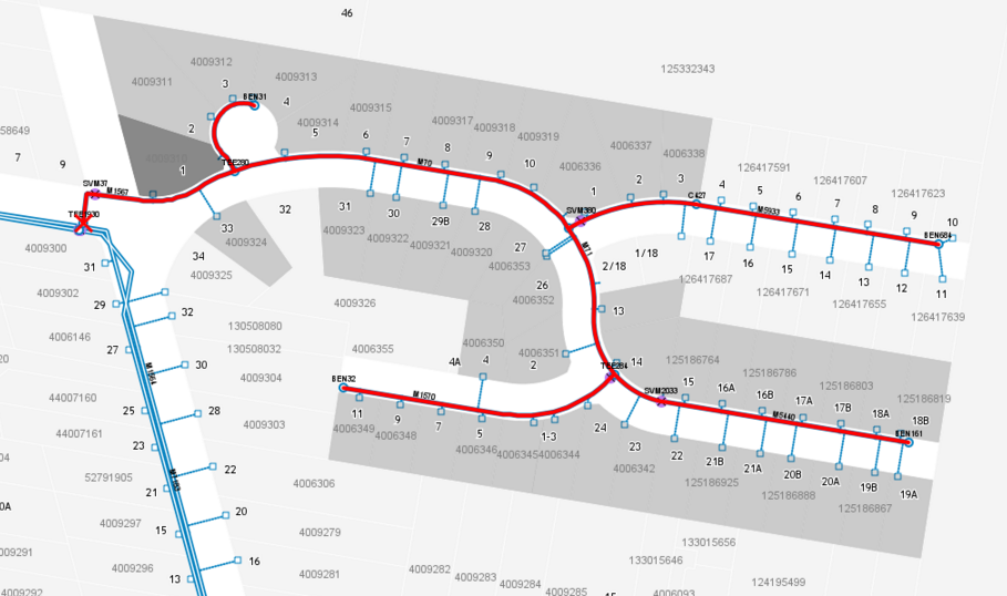
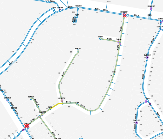
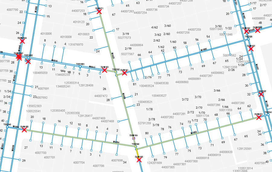
Isolation Trace
An Isolation trace is used to find the nearest valves or other isolation barrier asset classes.
The scenario is that we need to shut down the network and find the closes valves to define the closure extent
We want to shut down this network.
First step enable isolation mode to turn off all isolation nodes (valves) and select an edge in the network
Run the trace to see if the isolation nodes shut down our desired network
If we need a larger network, we can open a node using the continue tool on a valve and rerun the trace
And then select properties